Inverting the Unwanted
ZHEN X. YANG
Zhen X. Yang is a graduate student in his final year at the University of Toronto Daniels Faculty of Architecture, Landscape, and Design. His work and research focuses on computational design, digital fabrication, and artificial intelligence. Zhen has been a member of the Digital Fabrication Lab for 4 years and is experienced in CNC-Milling operations, a core fabrication technique for his work. He has published and presented a paper for ACSA, showcasing the collaborative Artificial Intelligence guide and exhibition he put together for the Eberhard Zeidler Library and the undergraduate course, Computation and Design. Zhen’s core interests lie in leveraging computation and digital fabrication to make possible the creation of complex geometries.
Read the article in PDF form here.
![]()
Figure 1. Photos taken of the same log from different heights and directions to assemble a photogrammetry scan, 2023. Zhen X. Yang.
Inverting the Unwanted presents a fabrication and building method for underutilized, small-diameter trees. Through the act of quartering, inverting, and joining a log, a standardized, yet unique column is formed. This simple rearrangement aims to take advantage of low-value, small-diameter trees that are constantly cut down as part of forestry thinning practices. Using this technique of log inversion leads to the capture of carbon that is otherwise released through the decomposition of the trees left on the ground after thinning. Furthermore, this value-added practice can supplant forestry income, and allow for ecological benefits through the extended aging of financially mature trees.
SKETCHY ORIGINS
This thesis originated out of the influences of my mentors and peers. I happened to be in the right place, at the right time, with the right skills, knowing the right people. The base idea came from Yuuko Tingyu Han, a close friend and colleague of mine since my undergraduate degree. One day she passed by my desk and discussed this idea she had with me, and we made a quick sketch. The basic premise was simple: Cut a log into quarters, and re-arrange those quarters so the corners face out, by doing this, the natural edges align beautifully, and the outer geometry becomes regularized. This idea made its way into our research semester with Zachary Mollica, my thesis advisor, who tasked us with creating building components with underutilized tree parts, such as the crown or roots. As I attempted to fabricate this column, some of the project rationale started to emerge. Through research, I learned how small-dimension trees are of low value and are typically cut down during forestry practices, which presented the prime material stock and opportunity for this project.
![]()
![]()
Figure 2. Initial sketches with Yuuko, 2023. Zhen X. Yang.
PHYSICAL PROTOTYPING
Throughout the year, the projected final product of my research continuously shifted. While initially conceived as a structural column, development continued, and it became a building system of columns, beams, and joints. Another path of inquiry with the technique envisioned it at a smaller scale, as a line of furniture pieces, lighting fixtures, and shelving systems. Regardless of application, the work has always been at a 1:1 scale—not a conscious choice, but one that seemed intuitive. The materials I’m working with - trees of around 3 - 5” diameter - are small enough to handle easily with hand and power tools. Working at this scale also provided benefits, such as accurately representing the building process and final product. It’s not like a small model of a building that encounters issues when it comes time for large-scale construction. Since I’m working in the intended final size, the only scaling up I’m doing is in quantity, by imagining how to efficiently automate the technique of inverting logs in a sawmill setting.
Six prototypes have been produced since the beginning of the project—each testing different techniques, materials, and approaches. The following is a guide to the tools and workflows I developed throughout the process.
![]()
![]()
![]()
Figure 3. Products of the first semester’s technical experiments. From left to right: 001 Mycelium Fill, 002 Exact Log, 003 Art Object, 2023. Zhen X. Yang.
DESIGNING TOOLS
Tool design has been key to the entire production process, the key issue that these inverted logs tackle is the non-uniformity of trees. The world works with dimensional lumber because it’s easy, the dimensions are standard, the materials are square, and are easy to work with. In the process of developing a product with a square exterior, I have to control these non-uniform geometries by building custom tools. These jigs can be organized by their main functions: cutting, CNC milling, and assembly.
Cutting Jigs
Prior to my research, Zac and his previous design-build class built some of the key jigs I utilized. I frequent two V-shaped log-cutting jigs—one running parallel to the blade for rip-cuts (cuts along the length of the tree), and one running perpendicular to the blade for cross-cuts (cutting through the diameter of the tree). These jigs, and future jigs of my design, fulfill two main purposes: they hold the log in place during cutting operations by preventing rolling, while also aligning the log to the cutting blade.
A key jig of my design is the Exact Cut Jig, which allows for free-form alignment of the log along a cut plane. This jig was developed out of a need for cutting custom lines along the log, which was a requirement of Prototype 002 - Exact Log. While the two aforementioned V-jigs developed by Zac’s class are convenient, the cut lines are always determined by how the log naturally falls into the V. This doesn’t allow for much customization in the angle of the cut plane. To produce strong columns, the distribution of mass should be ideally equal between the four quarters, which necessitates a custom cut line. These parameters led to the development of the Exact Cut Jig.
CNC JIGS
The CNC jigs are the most complex of all the jigs I build. They were developed to affix an already quartered log to the CNC bed, enabling the cutting of dovetails and other joinery. To understand these jigs, it’s necessary to understand some basic aspects of the CNC machine:
Three jigs were constructed to secure logs to the CNC bed, while also being a physical object to help me locate digital coordinate space in the real world. Quarter Log Clamp V1 and its successor, Quarter Log Clamp V2, function by clamping and spacing the log quarters on the CNC bed, allowing me to mill cutouts for a flitch plate insert. The latter is an improved version that allows for the milling of longer logs, to eventually build up to 8’ tall columns. The 4-axis CNC anchor is a manual version of a 4-axis CNC machine, allowing me to rotate the column and mill on all 4 faces.
![]()
![]()
Figure 4. Exact Cut Jig. The two V-shaped pieces supporting the log can be freely moved and secured onto the baseboard to adjust the cut line, 2023. Zhen X. Yang.
Figure 5. Zac’s rip-cut V jig from the summer design-build, 2023. Zhen X. Yang.
ASSEMBLY JIGS
The assembly jigs help constrain the inverted log during the assembly process. While the resulting assembled column is stable, the individual quarters are unwieldy (they’ve tipped over and fallen on my foot more than once). These assembly jigs hold the pieces in their corners until I can affix a base plate to the top and bottom. They also act as a casting mold for Prototype 001 - Mycelium Fill, and for future iterations with a concrete fill.
![]()
Figure 6. Quarter Log Clamp V2. This updated jig holds the log quarters at a 45-degree angle. It comes in four parts which allows it to hold onto longer pieces, 2024. Zhen X. Yang.
PHYGITAL
Prototype 002 - Exact Log, was a practice in digital to physical reproduction. The uncut log was photographed 56 times from multiple angles, and images were fed into photogrammetry software. Photogrammetry creates a 3D scan of an object by matching and locating overlapping photos using the recurring elements within the overlap. With the digital mesh of the log and its physical twin, I cut the log digitally, then matched those cuts physically on the real thing, demonstrating the ability to accurately cut the physical log to match the digital counterpart. This is a step in proving the ability to apply computational optimization processes to these prototypes. Other computational strategies also proved helpful: Galapagos and other evolutionary solvers were used to optimize for an even distribution of mass throughout the four quarters of the log, thus achieving a more structurally stable final state.
The most difficult part of this process was matching the physical prototype to the digital scan, as it required me to work precisely with the non-uniform geometry of the log. Non-uniform geometries made even simple tasks—such as drawing a straight line—difficult because they require the line to be projected onto an uneven, bumpy surface. The general workflow involved:
Between these reference points and laser markings, I was able to divide the log according to the digital model. Then, using the jig, I was able to cut the log exactly down those lines.
![]()
![]()
Figure 7. Laser projection allows the drawing of cut lines onto the log’s surface, 2023. Zhen X. Yang.
Figure 8. Log on bandsaw—measured, marked, and set on the jig right before cutting, 2023. Zhen X. Yang.
DIGITAL DREAMS
Computation has been integral to scaling my thesis. Two main computational techniques that emerged from my work include a log generator and a forest generator. Log Generator is a grasshopper script that generates randomized logs that are then cut into quarters and inverted to form the final product. The randomization of log geometry and the cut planes ensures diversity in output generations somewhat reflective of the natural growth of trees. The randomization process includes multiple parameters. When you think about a tree and how it grows, there are some consistent properties:
By randomizing these parameters, the script recursively produces geometrically diverse logs. This provides me with an unlimited, synthetic dataset of logs to test with. The primary issue with this method is that the generated logs do not have more extreme deviations from a typical log shape, which natural trees will have. Things such as weird kinks and bends, knots, and uneven growth, are much-needed future additions to the logs generated by the script. Including those will give a far more accurate representation of log generation.
Forest Generator is a Grasshopper script that generates a 1km x 1km grid and populates it with trees consistent with the forest composition of Ontario. The goal of this script is to demonstrate how and why thinning operations are performed in managed forests. (This script was a case of “I thought this would take one hour and it ended up taking one day”).
A few key points to the function of this Grasshopper script:
In a way, these scripts are also jigs that build a foundation for my other work. In the case of the Log Generator, the script allows me to randomize logs that I can perform operations on to validate my methodology of log inversion, while the Forest Generator provides the base image for me to start diagramming and explaining some of the concepts behind the log inversion technique. These digital jigs are not the end goal, but a step towards the final output.
The process in my thesis project has been a gradient through the spectrum of tool design. I have made both higher-end jigs tailored for mass production and low-end tests. Throughout all this, I aimed for a middle ground, designing tools that were advanced where it mattered, and simple enough that I didn’t spend too much time building tools instead of projects.
While the final prototypes that have come out of my project appear simple, they have emerged from complex processes—each testing a variety of methods beyond what is reflected in the prototype’s appearance. From the development of jigs, to precise measurements and computational analysis, to intricate joinery, the process of producing these works often goes beyond the physical artifact.
Zhen X. Yang is a graduate student in his final year at the University of Toronto Daniels Faculty of Architecture, Landscape, and Design. His work and research focuses on computational design, digital fabrication, and artificial intelligence. Zhen has been a member of the Digital Fabrication Lab for 4 years and is experienced in CNC-Milling operations, a core fabrication technique for his work. He has published and presented a paper for ACSA, showcasing the collaborative Artificial Intelligence guide and exhibition he put together for the Eberhard Zeidler Library and the undergraduate course, Computation and Design. Zhen’s core interests lie in leveraging computation and digital fabrication to make possible the creation of complex geometries.
Read the article in PDF form here.
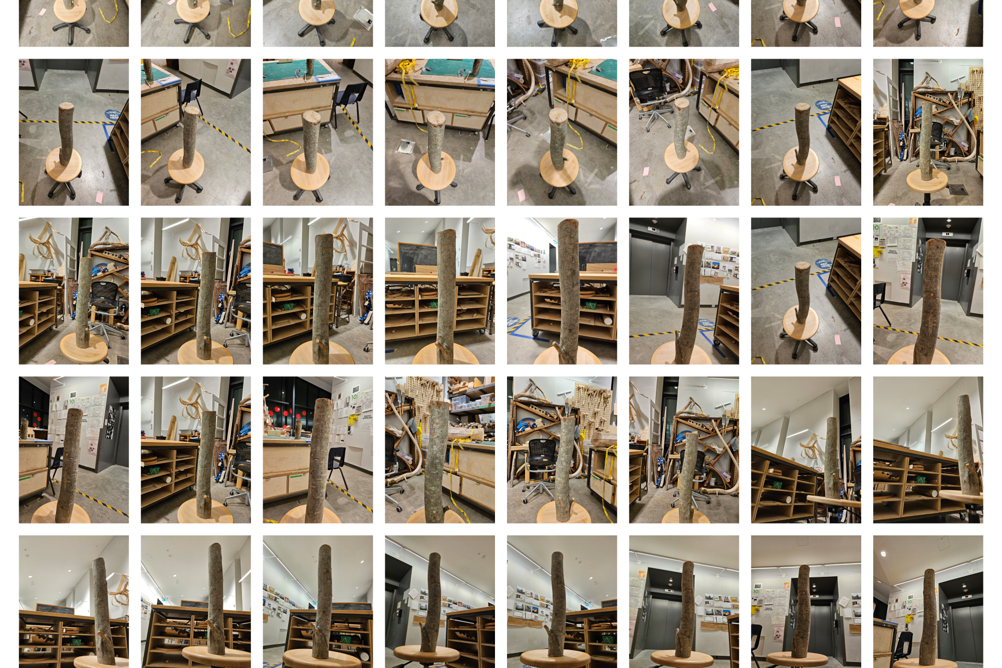
Figure 1. Photos taken of the same log from different heights and directions to assemble a photogrammetry scan, 2023. Zhen X. Yang.
Inverting the Unwanted presents a fabrication and building method for underutilized, small-diameter trees. Through the act of quartering, inverting, and joining a log, a standardized, yet unique column is formed. This simple rearrangement aims to take advantage of low-value, small-diameter trees that are constantly cut down as part of forestry thinning practices. Using this technique of log inversion leads to the capture of carbon that is otherwise released through the decomposition of the trees left on the ground after thinning. Furthermore, this value-added practice can supplant forestry income, and allow for ecological benefits through the extended aging of financially mature trees.
SKETCHY ORIGINS
This thesis originated out of the influences of my mentors and peers. I happened to be in the right place, at the right time, with the right skills, knowing the right people. The base idea came from Yuuko Tingyu Han, a close friend and colleague of mine since my undergraduate degree. One day she passed by my desk and discussed this idea she had with me, and we made a quick sketch. The basic premise was simple: Cut a log into quarters, and re-arrange those quarters so the corners face out, by doing this, the natural edges align beautifully, and the outer geometry becomes regularized. This idea made its way into our research semester with Zachary Mollica, my thesis advisor, who tasked us with creating building components with underutilized tree parts, such as the crown or roots. As I attempted to fabricate this column, some of the project rationale started to emerge. Through research, I learned how small-dimension trees are of low value and are typically cut down during forestry practices, which presented the prime material stock and opportunity for this project.


Figure 2. Initial sketches with Yuuko, 2023. Zhen X. Yang.
PHYSICAL PROTOTYPING
Throughout the year, the projected final product of my research continuously shifted. While initially conceived as a structural column, development continued, and it became a building system of columns, beams, and joints. Another path of inquiry with the technique envisioned it at a smaller scale, as a line of furniture pieces, lighting fixtures, and shelving systems. Regardless of application, the work has always been at a 1:1 scale—not a conscious choice, but one that seemed intuitive. The materials I’m working with - trees of around 3 - 5” diameter - are small enough to handle easily with hand and power tools. Working at this scale also provided benefits, such as accurately representing the building process and final product. It’s not like a small model of a building that encounters issues when it comes time for large-scale construction. Since I’m working in the intended final size, the only scaling up I’m doing is in quantity, by imagining how to efficiently automate the technique of inverting logs in a sawmill setting.
Six prototypes have been produced since the beginning of the project—each testing different techniques, materials, and approaches. The following is a guide to the tools and workflows I developed throughout the process.
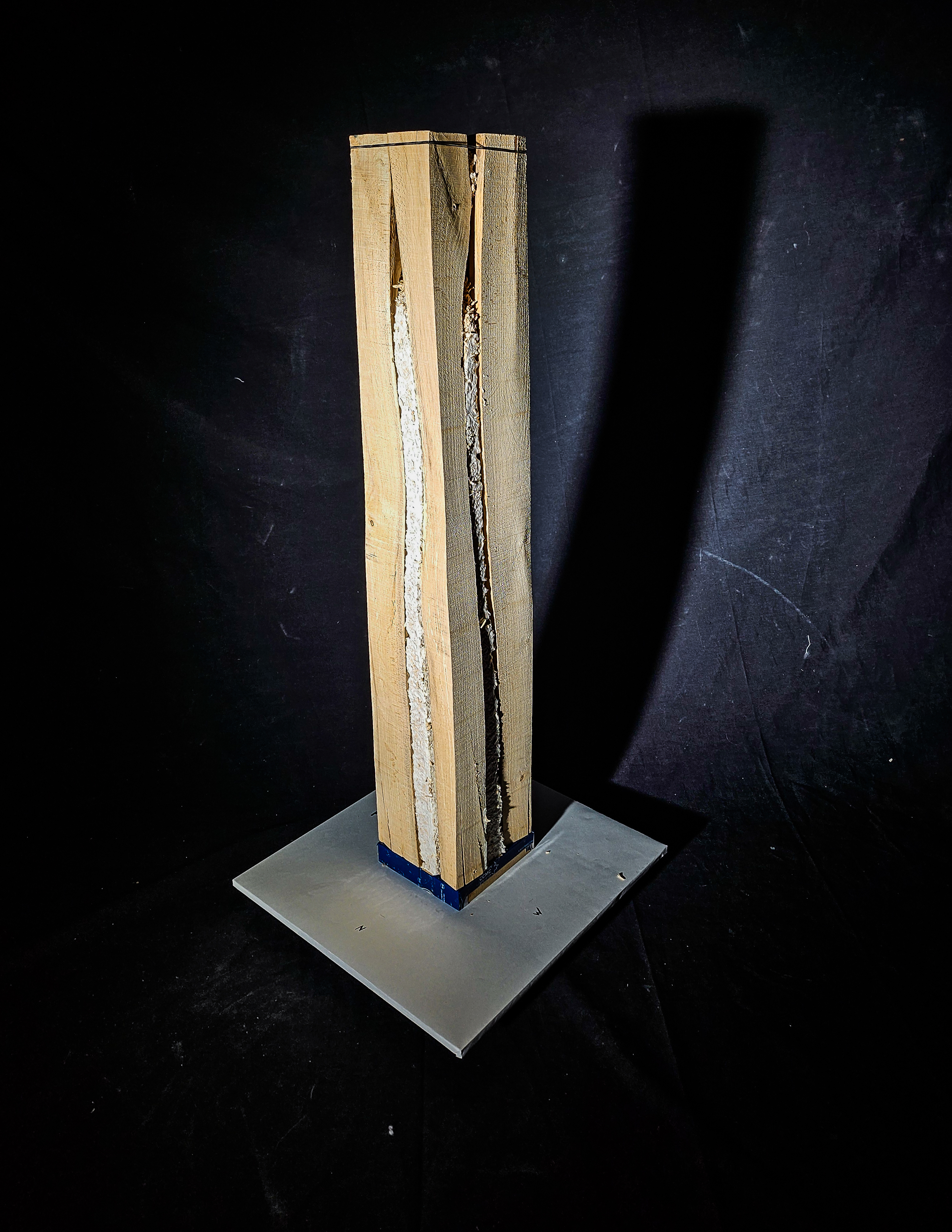
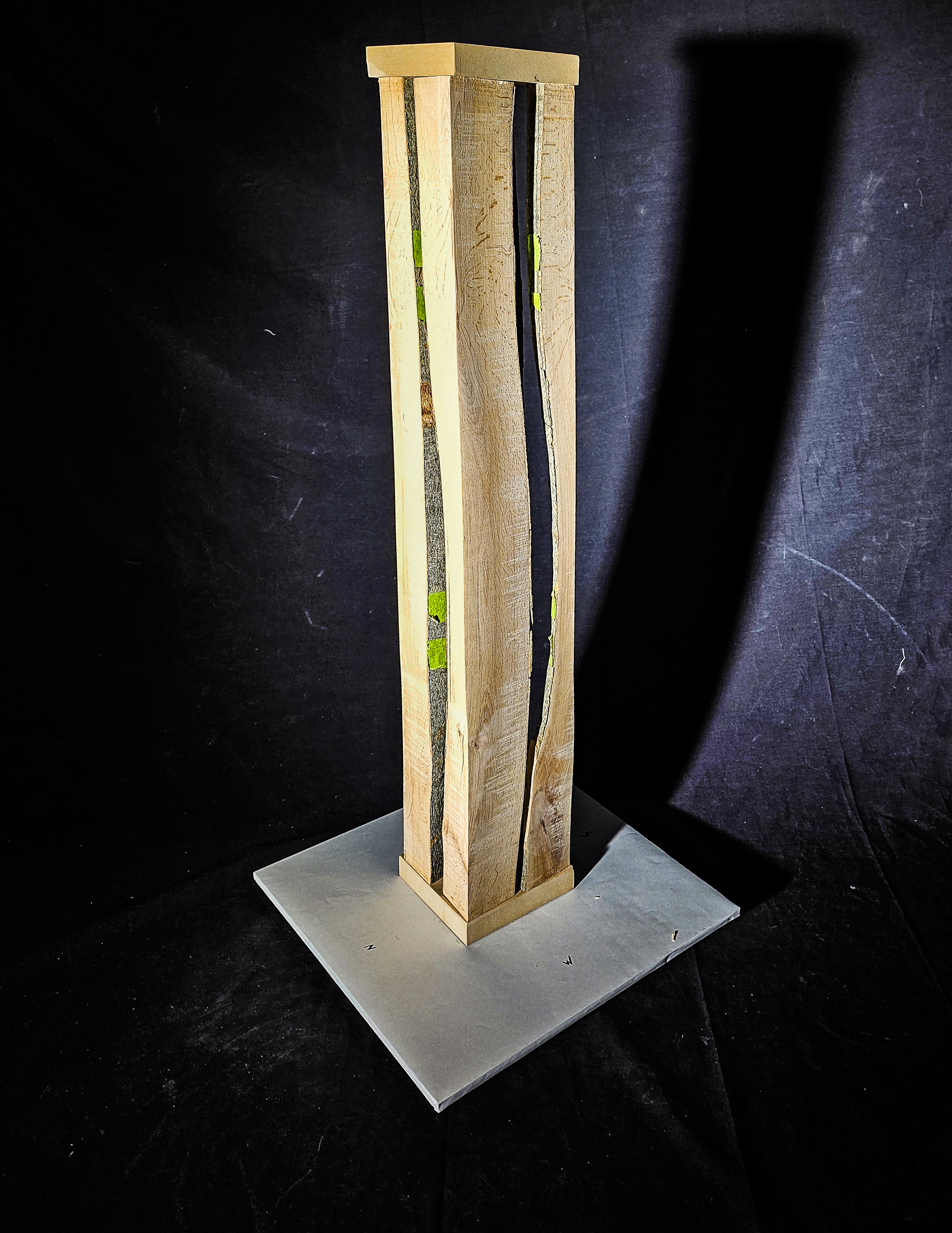

Figure 3. Products of the first semester’s technical experiments. From left to right: 001 Mycelium Fill, 002 Exact Log, 003 Art Object, 2023. Zhen X. Yang.
DESIGNING TOOLS
Tool design has been key to the entire production process, the key issue that these inverted logs tackle is the non-uniformity of trees. The world works with dimensional lumber because it’s easy, the dimensions are standard, the materials are square, and are easy to work with. In the process of developing a product with a square exterior, I have to control these non-uniform geometries by building custom tools. These jigs can be organized by their main functions: cutting, CNC milling, and assembly.
Cutting Jigs
Prior to my research, Zac and his previous design-build class built some of the key jigs I utilized. I frequent two V-shaped log-cutting jigs—one running parallel to the blade for rip-cuts (cuts along the length of the tree), and one running perpendicular to the blade for cross-cuts (cutting through the diameter of the tree). These jigs, and future jigs of my design, fulfill two main purposes: they hold the log in place during cutting operations by preventing rolling, while also aligning the log to the cutting blade.
A key jig of my design is the Exact Cut Jig, which allows for free-form alignment of the log along a cut plane. This jig was developed out of a need for cutting custom lines along the log, which was a requirement of Prototype 002 - Exact Log. While the two aforementioned V-jigs developed by Zac’s class are convenient, the cut lines are always determined by how the log naturally falls into the V. This doesn’t allow for much customization in the angle of the cut plane. To produce strong columns, the distribution of mass should be ideally equal between the four quarters, which necessitates a custom cut line. These parameters led to the development of the Exact Cut Jig.
CNC JIGS
The CNC jigs are the most complex of all the jigs I build. They were developed to affix an already quartered log to the CNC bed, enabling the cutting of dovetails and other joinery. To understand these jigs, it’s necessary to understand some basic aspects of the CNC machine:
-
The CNC bed is a vacuum-enabled metal bed, with a board of porous MDF sitting above it. The vacuum pulls sheet material down and keeps it in place while the mill operates. This is perilous for milling log quarters because the log quarters are small, and low surface area = less suction strength.
-
The CNC machine is a dumb machine, it will do whatever you tell it to. It has only a conception of what is on the bed if you model and program it. If something goes wrong during the process, the CNC will continue to run until it breaks or encounters some fatal error.
-
The CNC machine can mill exact toolpaths, however, the operator (me) needs to align the physical object to the exact location shown in the digital model. The easiest way to do this is to use the CNC machine itself to draw a bounding box of where the material needs to be.
Three jigs were constructed to secure logs to the CNC bed, while also being a physical object to help me locate digital coordinate space in the real world. Quarter Log Clamp V1 and its successor, Quarter Log Clamp V2, function by clamping and spacing the log quarters on the CNC bed, allowing me to mill cutouts for a flitch plate insert. The latter is an improved version that allows for the milling of longer logs, to eventually build up to 8’ tall columns. The 4-axis CNC anchor is a manual version of a 4-axis CNC machine, allowing me to rotate the column and mill on all 4 faces.

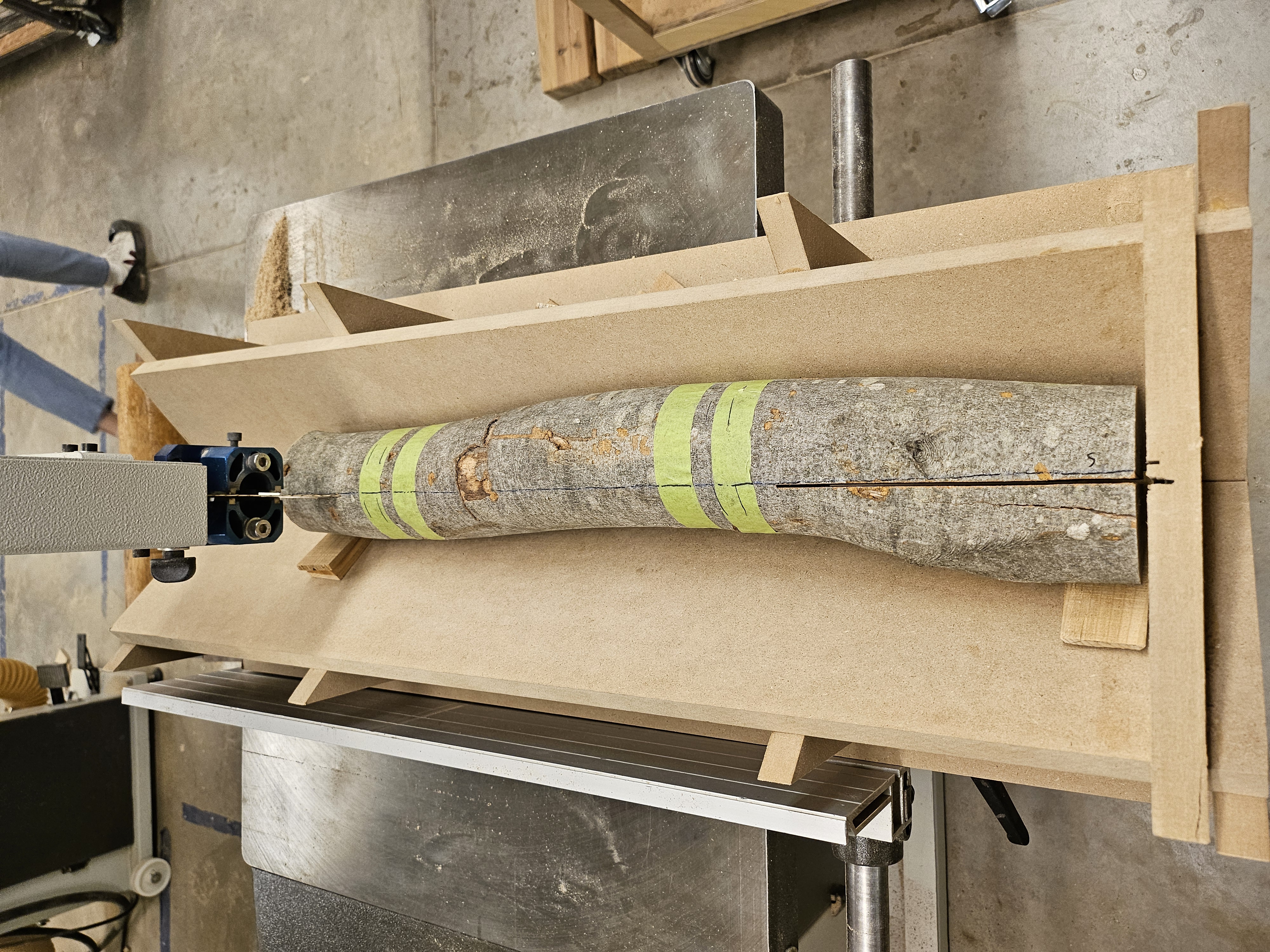
Figure 4. Exact Cut Jig. The two V-shaped pieces supporting the log can be freely moved and secured onto the baseboard to adjust the cut line, 2023. Zhen X. Yang.
Figure 5. Zac’s rip-cut V jig from the summer design-build, 2023. Zhen X. Yang.
ASSEMBLY JIGS
The assembly jigs help constrain the inverted log during the assembly process. While the resulting assembled column is stable, the individual quarters are unwieldy (they’ve tipped over and fallen on my foot more than once). These assembly jigs hold the pieces in their corners until I can affix a base plate to the top and bottom. They also act as a casting mold for Prototype 001 - Mycelium Fill, and for future iterations with a concrete fill.

Figure 6. Quarter Log Clamp V2. This updated jig holds the log quarters at a 45-degree angle. It comes in four parts which allows it to hold onto longer pieces, 2024. Zhen X. Yang.
PHYGITAL
Prototype 002 - Exact Log, was a practice in digital to physical reproduction. The uncut log was photographed 56 times from multiple angles, and images were fed into photogrammetry software. Photogrammetry creates a 3D scan of an object by matching and locating overlapping photos using the recurring elements within the overlap. With the digital mesh of the log and its physical twin, I cut the log digitally, then matched those cuts physically on the real thing, demonstrating the ability to accurately cut the physical log to match the digital counterpart. This is a step in proving the ability to apply computational optimization processes to these prototypes. Other computational strategies also proved helpful: Galapagos and other evolutionary solvers were used to optimize for an even distribution of mass throughout the four quarters of the log, thus achieving a more structurally stable final state.
The most difficult part of this process was matching the physical prototype to the digital scan, as it required me to work precisely with the non-uniform geometry of the log. Non-uniform geometries made even simple tasks—such as drawing a straight line—difficult because they require the line to be projected onto an uneven, bumpy surface. The general workflow involved:
-
Drawing reference points on the ends of the log. Cut logs eventually develop a split within them called shake, which is a natural separation of the wood fibers caused by bacteria. Using the shake as a reference, I was able to accurately draw cut lines onto the physical log.
-
Lasers. Since the log is uneven it is extremely difficult to draw a straight line on it to represent where my cut should go. Lasers projected that line onto the log and assisted me with marking it exactly.
Between these reference points and laser markings, I was able to divide the log according to the digital model. Then, using the jig, I was able to cut the log exactly down those lines.
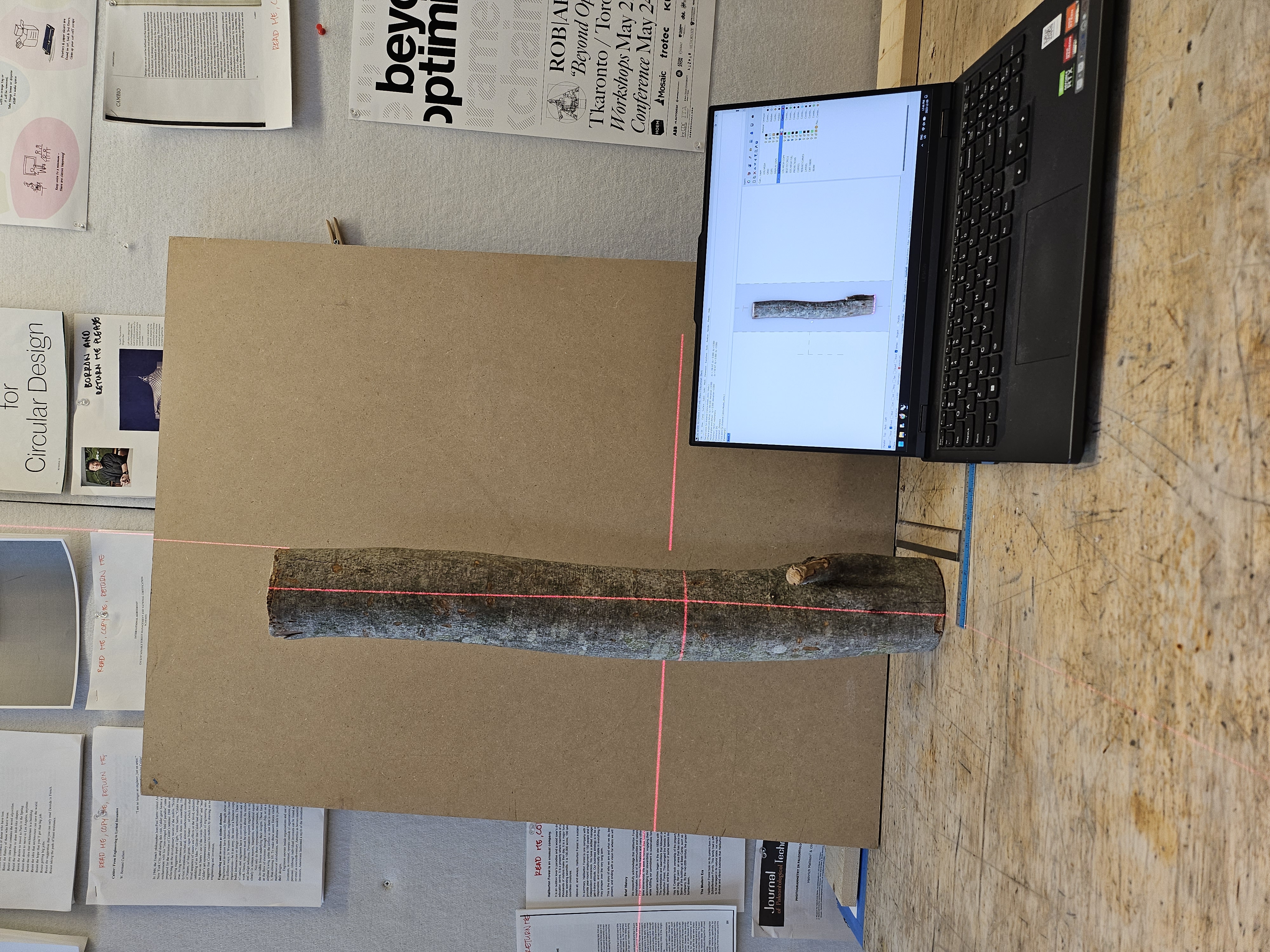
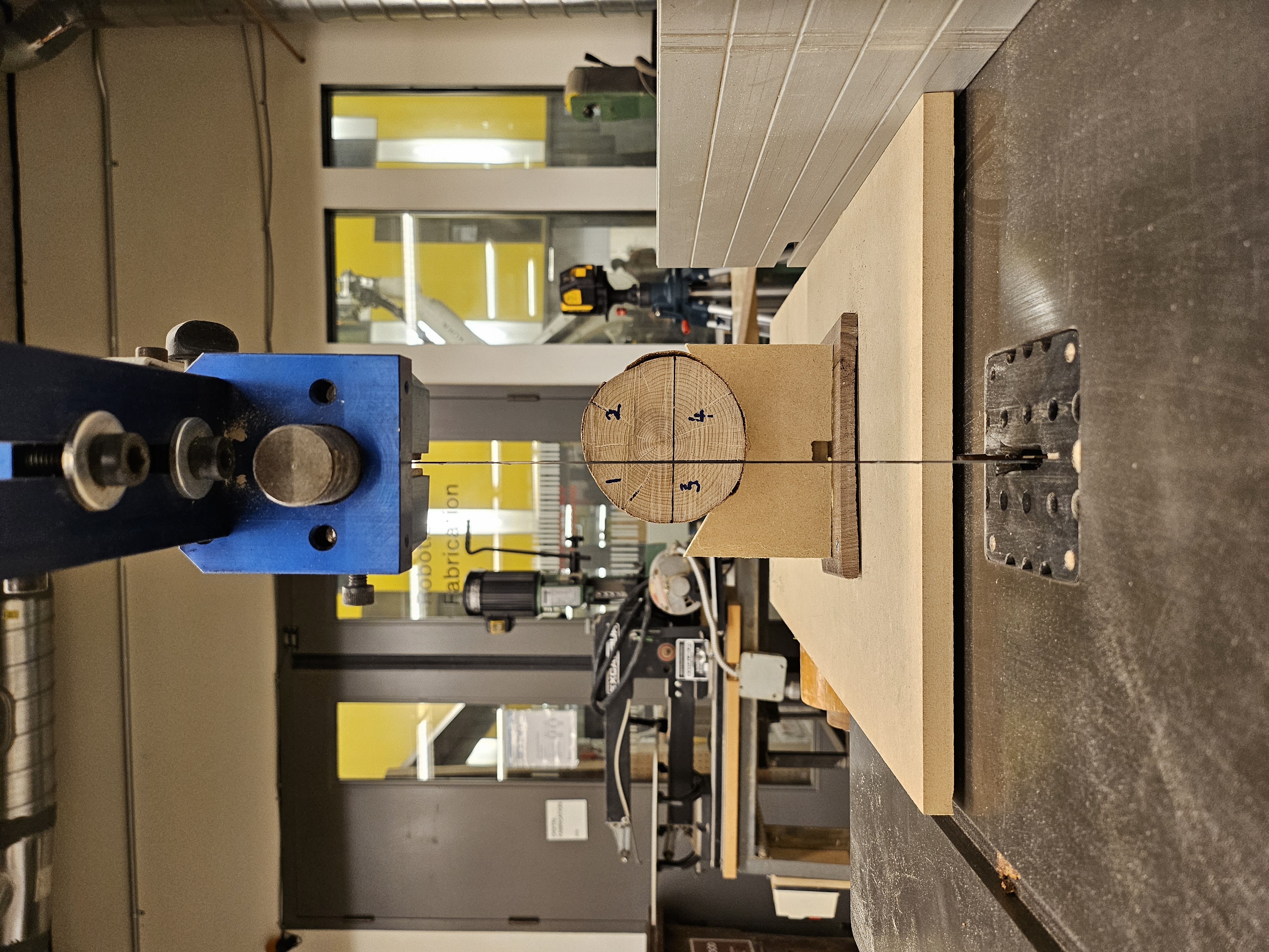
Figure 7. Laser projection allows the drawing of cut lines onto the log’s surface, 2023. Zhen X. Yang.
Figure 8. Log on bandsaw—measured, marked, and set on the jig right before cutting, 2023. Zhen X. Yang.
DIGITAL DREAMS
Computation has been integral to scaling my thesis. Two main computational techniques that emerged from my work include a log generator and a forest generator. Log Generator is a grasshopper script that generates randomized logs that are then cut into quarters and inverted to form the final product. The randomization of log geometry and the cut planes ensures diversity in output generations somewhat reflective of the natural growth of trees. The randomization process includes multiple parameters. When you think about a tree and how it grows, there are some consistent properties:
-
Tree diameters are typically consistent
-
Tree diameters decrease at increasing height
-
Trees do not grow straight up but deviate slightly in X and Y directions
-
Tree rings are not perfectly circular, and have knots and branches that change the geometry of the tree ring
By randomizing these parameters, the script recursively produces geometrically diverse logs. This provides me with an unlimited, synthetic dataset of logs to test with. The primary issue with this method is that the generated logs do not have more extreme deviations from a typical log shape, which natural trees will have. Things such as weird kinks and bends, knots, and uneven growth, are much-needed future additions to the logs generated by the script. Including those will give a far more accurate representation of log generation.
Forest Generator is a Grasshopper script that generates a 1km x 1km grid and populates it with trees consistent with the forest composition of Ontario. The goal of this script is to demonstrate how and why thinning operations are performed in managed forests. (This script was a case of “I thought this would take one hour and it ended up taking one day”).
A few key points to the function of this Grasshopper script:
-
The 3D tree geometry is all AI-generated, at the time of making the script, I discovered LUMA.AI, an AI model that allows you to prompt and generate a 3D mesh model. By consulting a list of the most common tree species in Ontario, I generated the top 7 most populous species using the AI model and cross-checked them against photos. The results are decently accurate, and although the model resolution is low, it is acceptable for diagramming purposes. Too detailed of a model is unnecessary and would explode my computer.
-
This script takes the 3D tree models and places them randomly on the grid, while applying a random scale and rotation so that there is variation between the same species of tree.
-
The final tree composition reflects the average forest composition in Ontario, for example, a 1km x 1km plot of land will consist of roughly 35% black spruce based on provincial statistics. Therefore, if there are 100 trees, 35 of them would be black spruce. (While I advocate for building jigs that are “just enough” for the purpose at hand, sometimes I get distracted and go overboard. This detail actually took the longest time to script, and isn’t really all that important. Do as I say, not as I do.)
In a way, these scripts are also jigs that build a foundation for my other work. In the case of the Log Generator, the script allows me to randomize logs that I can perform operations on to validate my methodology of log inversion, while the Forest Generator provides the base image for me to start diagramming and explaining some of the concepts behind the log inversion technique. These digital jigs are not the end goal, but a step towards the final output.
The process in my thesis project has been a gradient through the spectrum of tool design. I have made both higher-end jigs tailored for mass production and low-end tests. Throughout all this, I aimed for a middle ground, designing tools that were advanced where it mattered, and simple enough that I didn’t spend too much time building tools instead of projects.
While the final prototypes that have come out of my project appear simple, they have emerged from complex processes—each testing a variety of methods beyond what is reflected in the prototype’s appearance. From the development of jigs, to precise measurements and computational analysis, to intricate joinery, the process of producing these works often goes beyond the physical artifact.
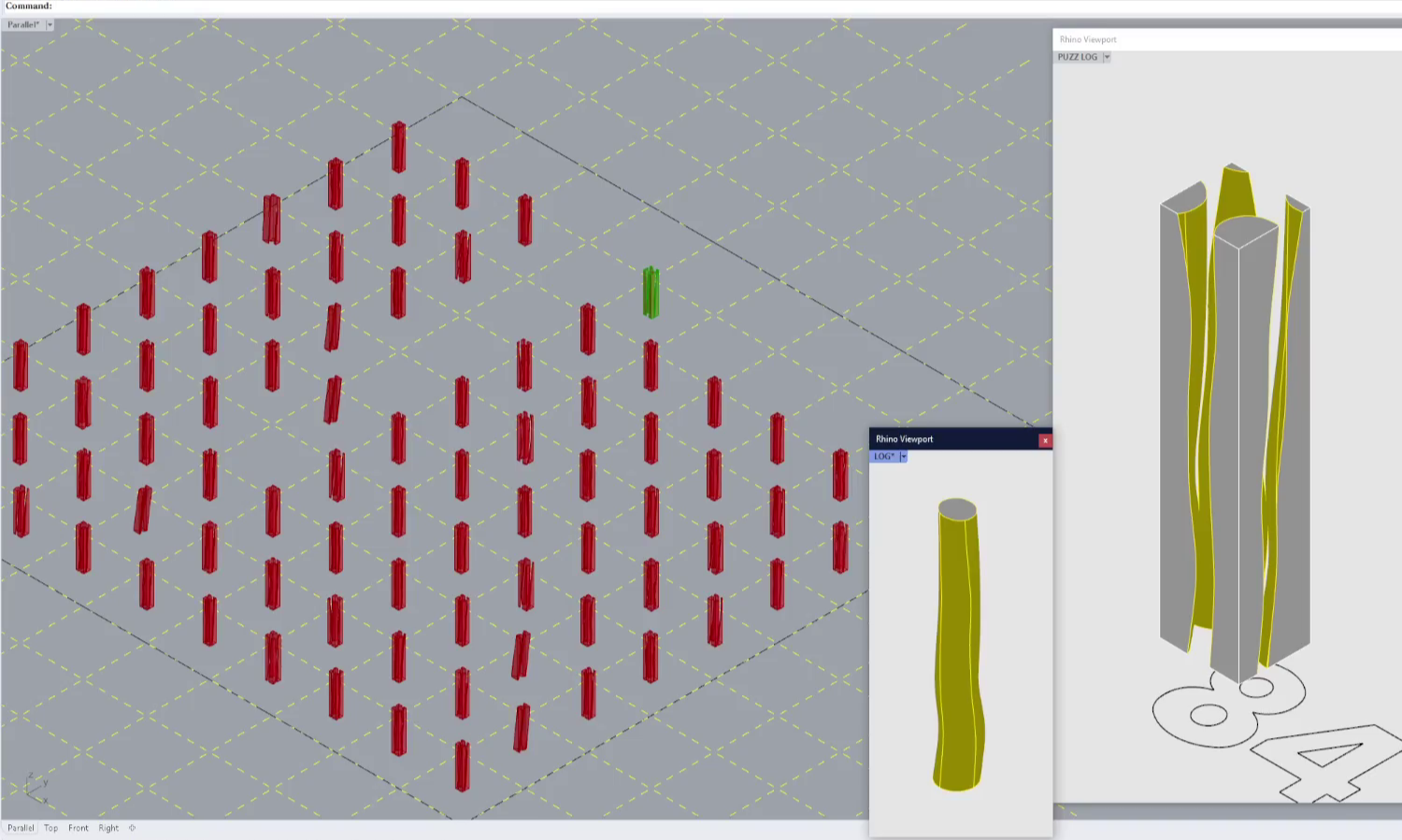
Figure 9. Log Generator generating random log 84/100 in the grid of logs from previous generations, 2024. Zhen X. Yang.

